Toyota CH-R Manual de Taller: Ubicación De Las Piezas
UBICACIÓN DE LAS PIEZAS
ILUSTRACIÓN
|
*A |
Con luz interior de la puerta |
- |
- |
|
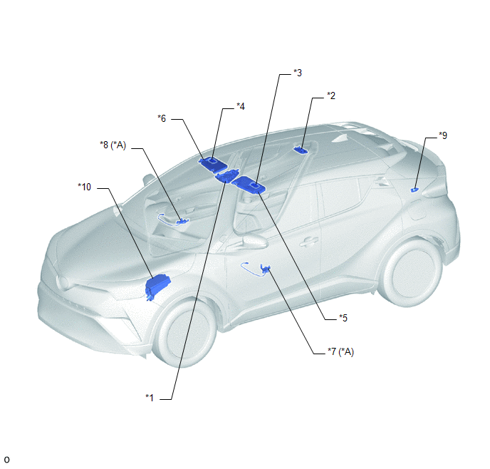
*1 |
CONJUNTO DE LA LUZ DE LECTURA DE MAPAS |
*2 |
CONJUNTO DE LA LUZ INTERIOR N° 1 |
|
*3 |
CONJUNTO DE LA LUZ DE CORTESÍA IZQUIERDO |
*4 |
CONJUNTO DE LA LUZ DE CORTESÍA DERECHO |
|
*5 |
CONJUNTO DEL PARASOL IZQUIERDO |
*6 |
CONJUNTO DEL PARASOL DERECHO |
|
*7 |
CONJUNTO DE LA LUZ INTERIOR N° 1 IZQUIERDA (LUZ AMBIENTAL DE LA PUERTA IZQUIERDA) |
*8 |
CONJUNTO DE LA LUZ INTERIOR N° 1 DERECHA (LUZ AMBIENTAL DE LA PUERTA DERECHA) |
|
*9 |
CONJUNTO DE LA LUZ DEL COMPARTIMIENTO DE EQUIPAJES IZQUIERDO N° 1 |
*10 |
BLOQUE DE RELÉS DEL COMPARTIMIENTO DEL MOTOR N° 1 |
ILUSTRACIÓN
|
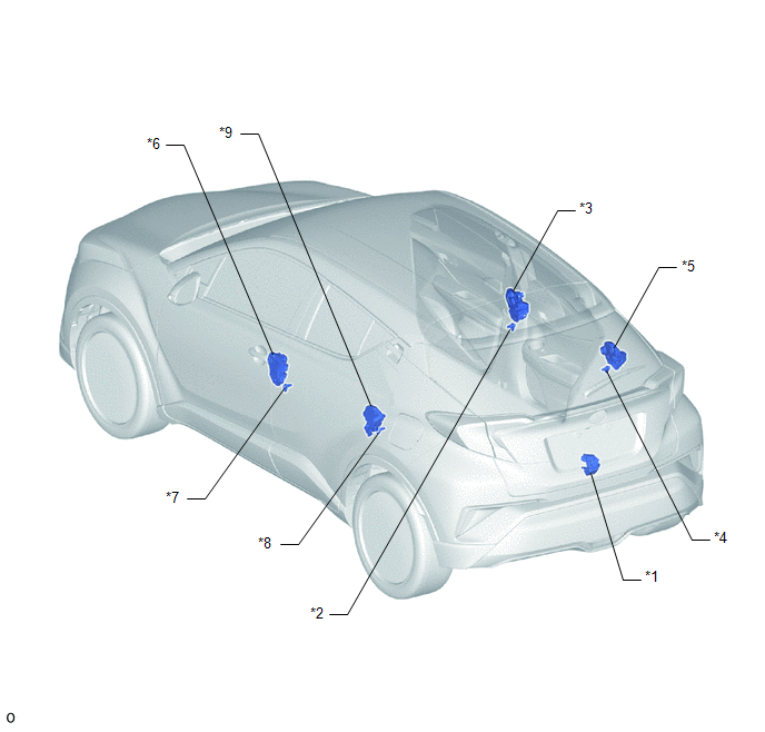
*1 |
CONJUNTO DE LA CERRADURA DE LA PUERTA DEL MALETERO |
*2 |
CONJUNTO DEL INTERRUPTOR DE LA LUZ DE CORTESÍA DE LA PUERTA DELANTERA DERECHA |
|
*3 |
CONJUNTO DE LA CERRADURA DE LA PUERTA DELANTERA DERECHA CON MOTOR |
*4 |
CONJUNTO DEL INTERRUPTOR DE LA LUZ DE CORTESÍA DE LA PUERTA TRASERA DERECHA |
|
*5 |
CONJUNTO DE LA CERRADURA DE LA PUERTA TRASERA DERECHA CON MOTOR |
*6 |
CONJUNTO DE LA CERRADURA DE LA PUERTA DELANTERA IZQUIERDA CON MOTOR |
|
*7 |
CONJUNTO DEL INTERRUPTOR DE LA LUZ DE CORTESÍA DE LA PUERTA DELANTERA IZQUIERDA |
*8 |
CONJUNTO DEL INTERRUPTOR DE LA LUZ DE CORTESÍA DE LA PUERTA TRASERA IZQUIERDA |
|
*9 |
CONJUNTO DE LA CERRADURA DE LA PUERTA TRASERA IZQUIERDA CON MOTOR |
- |
- |
ILUSTRACIÓN
|
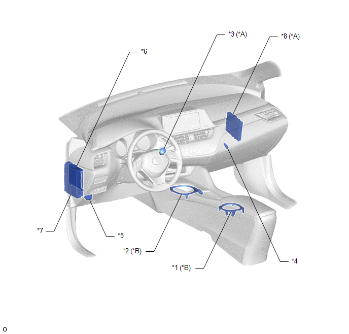
*A |
Con sistema de llave inteligente |
*B |
Con luz interior de la puerta |
|
*1 |
EMBELLECEDOR DE LA MOLDURA DE ACABADO CENTRAL DEL GRUPO DE INSTRUMENTOS (LUZ DEL SUJETAVASOS N° 2) |
*2 |
EMBELLECEDOR DE LA MOLDURA DE ACABADO DEL GRUPO DE INSTRUMENTOS (LUZ DEL SUJETAVASOS N° 1) |
|
*3 |
INTERRUPTOR DEL MOTOR |
*4 |
CONJUNTO DE LA LUZ DE LA GUANTERA |
|
*5 |
DLC3 |
*6 |
ECU PRINCIPAL DE LA CARROCERÍA (ECU DE LA RED MÚLTIPLEX DE LA CARROCERÍA) |
|
*7 |
CONJUNTO DEL BLOQUE DE EMPALMES DEL PANEL DE INSTRUMENTOS - FUSIBLE ECU-ACC - FUSIBLE ECU-IG1 N° 4 - FUSIBLE DOME - RELÉ ACC - RELÉ IG1 N° 1 - RELÉ DE CORTE DE LA LUZ DEL TECHO |
*8 |
ECU DE CERTIFICACIÓN (CONJUNTO DE LA ECU DE LA LLAVE INTELIGENTE) |
 Medidas De Precaución
MEDIDAS DE PRECAUCIÓN
MODOS DEL INTERRUPTOR DE ENCENDIDO
(a) El tipo de interruptor de encendido empleado en este modelo varía según las
características del vehículo. En la siguiente tabla se ...
 Cómo Proceder A La Localización De Averías
PRECAUCIÓN / AVISO / OBSERVACIÓN
OBSERVACIÓN:
Siga los siguientes procedimientos para localizar las averías del sistema
de iluminación.
*: Utilice el Techstream.
PROCEDIM ...
Otros materiales:
Toyota CH-R Manual de Taller > Engranaje De Dirección: Extracción
EXTRACCIÓN
PRECAUCIÓN / AVISO / OBSERVACIÓN
Los procedimientos necesarios (ajuste, calibración, inicialización o registro)
que deben realizarse después de retirar, instalar o sustituir piezas durante la
extracción/Instalación del conjunto del engranaje de dirección se muestran a conti ...
Toyota CH-R Manual de Taller > Sistema De Supervisión De Punto Ciego: Circuito abierto en el indicador del espejo exterior (maestro) (C1AB4)
DESCRIPCIÓN
Este DTC se almacena cuando el sensor de supervisión de punto ciego izquierdo
(maestro) detecta un circuito abierto en el indicador del espejo retrovisor exterior
izquierdo.
N° de DTC
Elemento detectado
Condición de detección del DTC
...
Toyota C-HR (AX20) 2023-2026 Manual del propetario
Toyota CH-R Manual del propetario
- Para su información
- índice de imágenes
- En aras de la seguridad
- Conjunto de instrumentos
- Funcionamiento de cada componente
- Conducción
- Sistema de audio
- Características interiores
- Mantenimiento y cuidados
- En caso de problemas
- Especificaciones del vehículo
- índice
Toyota CH-R Manual de Taller
- Asistencia Al Estacionamiento / Supervisión
- Audio / Vídeo
- Comunicación Móvil
- Pantalla De Navegación / Información Múltiple
- Columna De Dirección
- Engranaje / Varillaje De La Dirección
- Sistemas De Dirección Asistida
- Claxon
- Espejos Retrovisores (ext)
- Guarnición / Paneles Exteriores
- Iluminación (ext)
- Limpia / Lavaparabrisas
- Puertas / Portón Trasero
- Ventanillas / Cristales
- Freno De Estacionamiento
- Frenos (delanteros)
- Frenos (traseros)
- Sistema De Frenos (otros)
- Sistemas De Control Dinámico / Control De Frenos
- Batería / Carga 3zr-fae
- Distribución De La Electricidad
- Red
- Introducción
- Mantenimiento
- Anticolisión
- Asientos
- Bloqueo De Las Puertas
- Calefacción / Aire Acondicionado
- Cinturón De Seguridad
- Espejo Retrovisor (int)
- Guarnición / Paneles Interiores
- Iluminación (int)
- Medidor / Contador / Visualizador
- Sistema Antirrobo / Acceso Sin Llave
- Sistemas Complementarios De Sujeción
- Tomas De Corriente (int)
- Alineación / Diagnóstico De Manejo
- Control De La Presión De Los Neumáticos
- Neumáticos / Ruedas
- Suspensión Delantera
- Suspensión Trasera
- Eje De Transmisión / árbol De Transmisión
- Eje Y Diferencial
- K114 Cvt
0.0077